
We want to use modeling patterns where high-level behaviors from initial functional allocation are both modular and traceable to more detailed activity specifications. There are definite benefits, but there can be some frustrating points along the way. Our team recently hit a blocking issue that we had to troubleshoot when executing a simulation on a design.In this post, we'll walk through a subset of a model and show where we got stuck and how we worked through the troubleshooting. We'll start with a background to provide context for the initial model then show a set of state machines and activity diagrams where things broke during execution. Finally, we'll walk through our troubleshooting steps, how that fixed some things and exposed another issue, then show the 'solution'.Note: we're not working to get to a final solution. We're shooting to end at a point where the model contains an executable pattern for the design to continue to build on.We encourage behavioral modeling as soon as a modeling tool is used to capture a design. This leads to many benefits and lets the tool help do work for you. There's a good example of this at the end of the post. We will show a behavioral model leveraging the tool to create a recording of the execution as a sequence diagram. But first, we'll start with an overview of where we find things typically start - with a rudimentary model. We expect, practice, and teach this. Check out one of our previous posts: Just Model It - start simply and simply start
Ten minutes in PowerPoint won't get you a model. It can be useful if it generates consensus for the direction of the design. Sometimes things like this are delivered to you that have structural, behavioral, interface, and message detail. Sometimes you have to turn your head to the side a little and squint. In either case - it is a starting point for the conversation with stakeholders and something to refer back to when moving into more complex viewpoints.

Let's jump into Cameo and show a better starting point for structure and interface so we have a decent starting point in a modeling tool for behavioral modeling.[caption id="attachment_1856" align="aligncenter" width="606"]

click to enlarge[/caption]With just a half hour in the modeling tool, you can have a much more useful representation of structure, interfaces, connectivity, and communication. There is not yet any suggestion or specification of when different messages are sent/received or what happens when they are received. However, with blocks, ports, interface blocks, and signals, we have what we need to begin behavioral modeling.
We're also two clicks away from generating ICDs based on the design as shown in the IBD. Example Whitebox ICD below for the Mission Computer:[caption id="attachment_1858" align="aligncenter" width="750"]

click to enlarge[/caption]This is a great example of the design tool doing work for us. When you spend time modeling a system, the tools you use should leverage that model to produce value. In the Whitebox ICD table, it's now easy to see that there are ports that aren't typed. Go back to the previous image and look at the IBD. Did you notice that the ports connecting flight control to the mission computer should have been typed by an interface block and were not?
When you spend time modeling a system, the tools you use should leverage that model to produce value.
Different viewpoints are important for giving multiple perspectives into the same design. This is true not just for different stakeholders, but also for a systems engineer to analyze a design from those different perspectives.
Many times, high-level functions are delivered as part of customer requirements. There can even be problems when the functions are high-enough in abstraction where they don't over-constrain the design space. The difficulty is showing how high-level behaviors tie to lower-level system design detail while maintaining a consistent multi-leveled execution. Let's start with high-level system functions of Activate, Authenticate, Authorize, Collect, and Navigate and try to get things talking in a simulation.Our first step here is to add a simple state machine for the mission computer. The state machine begins in a locked Locked state and moves into the Authorize User state once it receives a userAuthentication signal.[caption id="attachment_1860" align="aligncenter" width="577"]
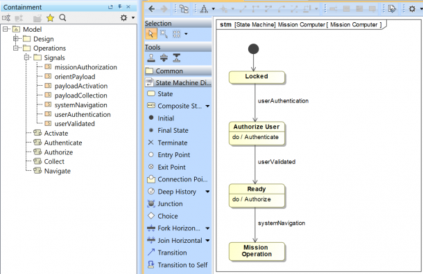
click to enlarge[/caption]When the mission computer initializes, it will sit in a locked state until it receives a userAuthentication message. We need to get the HMI to initiate this by sending that message over the interface between the two components. We'll initiate the simulation execution from the Mission Context block, so let's have it kick off the high-level activities:

We add the 'endMission' signal reception so it kicks off the Authenticate activity and then waits for other things to execute. The Authenticate activity action is put in the HMI swimlane so it is allocated appropriately to that block/part.
To finish out, we add the 'send signal' for the userAuthentication message via the login port.

For ease of monitoring, we add all the diagrams to the BDD. This forms a behavioral dashboard to watch the execution during simulation:[caption id="attachment_1869" align="aligncenter" width="717"]

click to enlarge[/caption]We expected to see a signal transmitted from HMI to Mission Computer. Look at the state machine: there is a trigger on the state transition out of the locked state. Reception of this signal transitions into the next state where it authorizes the user.
The send signal action activated correctly, but the message did not transmit over the expected interface.[caption id="attachment_1871" align="aligncenter" width="648"]

click to enlarge[/caption]The first attempt to patch things up began when we looked down in the Simulation Session window. See below - Notice how there is no instance of HMI created that could send that signal?

No big deal - create a state machine for HMI so a classifier behavior exists, so an instance is created.

Now we'll surely be good. Especially since the containment tree shows that the Authenticate action will execute in the context of HMI:

Even though we have an instance of HMI in the Session list, we still don't see the message go across the interface as expected.[caption id="attachment_1875" align="aligncenter" width="681"]

click to enlarge[/caption]
If you click on that last screenshot and look at the console - there's a clue. The specified port isn't in the context. To clarify: 'context' here is a generic term used by Cameo Simulation Toolkit, and is not referencing the 'mission context' element in our model. Looking at the Session list, we have an instance of HMI created. The activity looks like it's going to run in that context (from the note in the containment tree). However, everything still isn't aligned for execution.As with all things in engineering, context matters, and we can see that the simulation execution doesn't have the correct context for the activity to send the signal over the port. Time to re-work things a bit.Side Note: it can be difficult to determine why something appears in the containment tree like it does (as with the example above of the 'Authenticate' activity showing 'context HMI' in parentheses / gray text next to it). In this case, a little exploration in the specification and the containment tree showed us that when we dropped that activity in the swim lane of HMI on the activity diagram (which created an activity action typed by the Authenticate activity), it also created an 'allocate' relationship.
First, we take a half-step to the solution. We're not sure if it's going to work, but we create an activity under HMI to send the signal and have it be activated in two ways - first the same way as before...try to let the higher-level Mission Context directly call the activity. This doesn't work, but we've built a second way with a state machine for HMI that we can trigger manually with the Trigger drop-down above the Session sub-window as shown here:[caption id="attachment_1876" align="aligncenter" width="499"]

click to enlarge[/caption]Once we did that, the message sent over the interface and we can declare victory (but it was short-lived).[caption id="attachment_1877" align="aligncenter" width="624"]

click to enlarge[/caption]While the message was sent (green arrow), it did not get consumed at the Mission Computer, and therefore did not transition the state of the Mission Computer (red arrow). The message sends out over the proxy port twice - once for each end-point. And the message does not get consumed at the external boundary of the Mission Computer. We had a couple of options - full port instead of proxy, or split the port/interface. We opted for the latter.That's only part of the (second) fix. We still have to find a way for the Mission Context to stimulate the behavior of the HMI in the correct context. We need Mission Context to advance the HMI state machine. Normally, this would be the Operator interacting. But in this case, the Operator is outside of our Mission System SOI. To address this, we built some logic directly into the Mission Context to act as the test harness.[caption id="attachment_1878" align="aligncenter" width="506"]

click to enlarge and to see it running[/caption]
Many times we try multiple paths for a solution, and the 'fix' ends up being a combination of multiple different attempts/paths. This also means that parts of some paths (or entire attempts/paths) are added bloat to the model with no benefit that could cause confusion or issues in the future. Stay tuned for an upcoming post where we use our comparison tool to identify the changes between two snapshots of the model to explore all the relevant changes. For more information on the tool, click here: SEAM Baseline Plugin
There is work to be done: activities to create, signals to send/receive, and states to transition. The good news is we're well on the way to having everything in the initial PowerPoint graphic. We have an executable behavioral model where we can generate ICDs. Oh, and we saved the best for last: as the behavior executes, you can record a sequence diagram. This recording is stored in the model, and time-stamped. System designers and stakeholders can now see different as-run captured behaviors as the design progresses.

Please reach out to us via LinkedIn and let us know if you would have taken a different approach to what we have shown here - we'd love to hear from you. If the example models used in this post would be helpful to you and your team, we'd be happy to provide them for you to explore and modify. Ryan Platt (LinkedIn)Cliff Aldredge (LinkedIn)

©2025 Unmanned Systems Inc d.b.a Albers Aerospace, All Rights Reserved.